Update 27-02-2016: I have stopped working on this project, and therefore i no longer support the code/schematic and printed circuit board.
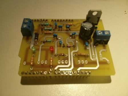
Update 20-12-2014: this arduino mppt charger shield is tested and works withTim Nolans version of the arduino sketch. The placement of the mosfet’s on th
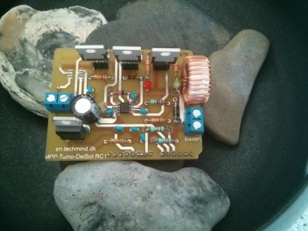
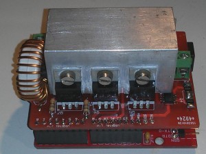 e circuit board was designed to fit to a Aluminium U profile.
Just make sure you don’t try to cool down the power from a 9 map solar panel, with this small aluminium Profile.
To do that, you need a bigger cooling plate. You can find a link in the article below for an example of how to use a salvaged pentium 4 cooling plate.
This project is inspired but the original Peak Power Tracker Battery Charger Project made by Tim Nolan. Unfortunally he’s website is down, so i will try to recover the specs and bilding material from his page.
The mppt solar charger with arduino is designed so a 12V (20 volt peak) solar panel can do the charging of a 12V lead acid battery.
Tim Nolan used a Arduino Duemilanove development board, in this project i have used both Duemilanove and Uno (r3) as the basic platform.
Tim Nolan used a Arduino Protoshield Kit for he’s development, i did that in my first version, but i became more and more happy for this project, and desided to make my own pcb layout based on Tim Nolan’s original project.
The project original consist of a number of files, most still have fully working link
- PPT Charger schematic (EagleCAD), this link still works: ArduinoSolar.pdf
- PPT Charger Hardware Description: link to ArduinoSolarHardware.txt broken, but this stll works: ArduinoSolarHardware.rtf
- PPT Charger Parts List still works : ArduinoSolarPartsList.txt
- PPT Charger Software (the original Arduino Sketch by Tim Nolan) is still online: ppt.pde
- PPT Charger Photos links are still working : Duemilanove and Protoshield, Prototshield back, Protoshield front
He made a article on http://www.homepower.com on how Peak Power Tracking works. The original article is still online: Peak Power Tracking article.pdf
More cooling options for te arduino mppt solar charger
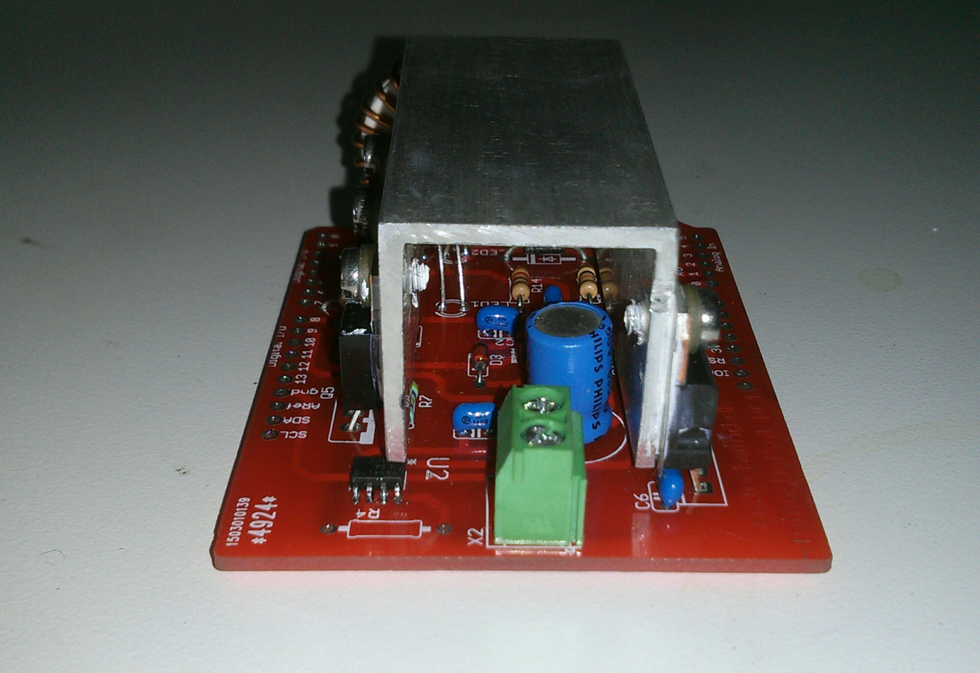
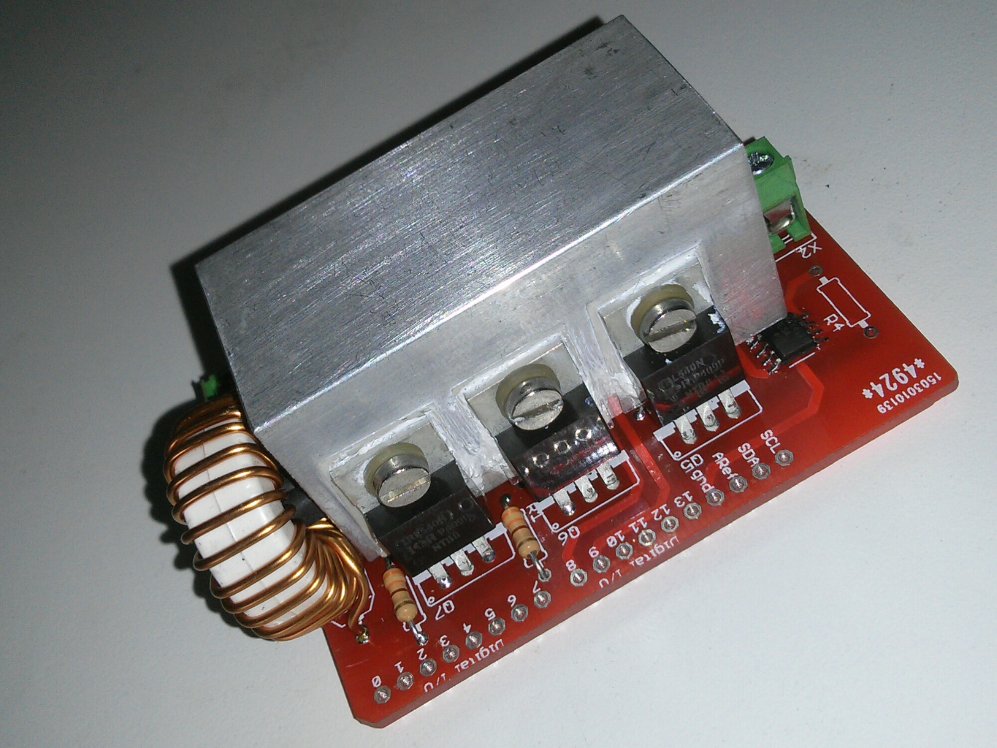
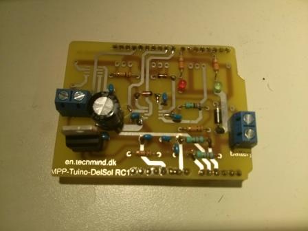
Open source pcb made for Tim nolan’s mppt solar charger
This is a version rc1 of the pcb, and i will try using irl540 MOSFET instead of irfz44
Download eagle pcb and schematic source files:
 Free
Free 

Hello, i’ve just found this nice pcb and as i undestood from article, is made based on a schematic from T. Nolan. Can you send me the schematic?I tried to access his website but is not working I have an arduino and some solar panels and i want to put them at work
  Thanks in advance
Hey, yes, there is some kind of fault in the pcb, the current sensor show – values, but think it can be changed in the sketch. The eagle files for the MPPT shield are now in a link
hey admin. i jsut downloaded the pcb layout., is there any error in pcb layout?
Hi,
are there still faults in the pcb?
We have downloaded the Eagle file and would like to use the pcb for a school project.
We have also found out, that you have made some pcbs.
Are there 2 pcbs left which you would like to sell to us
greets
Hey, the version for download is the fully working version and tested. Thinl i will make a short demo movie some day. I am sorry i don’t have any pcbs, i sometime consider to order some i China, as i have found them usefull in my other projects
Hello
thanks a lot for the reply.
Your Eagle files will be a big help for us to make our first Arduino project work.
We will try to etch a pcb with our pupils by ourself. This will give us less posibilities to make failures
For plan B i have ordered +-10 PCBs from the ‘Chinaman’
I think there will be some left over. If you are interested…
Happy to be able to Help You, i liked this projekt original started and shared by Tim Nolan a lot. So i desided to make the PCB, an also share it. Nice with China pcbs, i am Curious to see how the real produced print looks, so i am interested in one pcs if there is one left when You completed your project
we will see what we will get
Of course there will be some PCBs left over.
So we will call back when they have arrived.
Great maybe i will order some also before
post from china has just arived.
It’s unbelievable
They have send 12 beautifull PCBs for about 22Euro.
Can you see the email adress i have offered above?
So please send a note with your adress for shipping some of the PCBs we did not need.
Thanks again for your great work.
happy to be at help for your project and that the eagles files turned in to nice pcbs
I am curious to hear where you ordered it, it sounds like at great price.
Thanks a lot, i have send you a email
Dear Sir,
I have read you were ordered ready board from the ‘Chinaman’, is possible you can share the supplier that I can order a few samples from they too?
appreciated for your help
best regards,
Leann
The schematic is not opening what type of file is it? and i mean what’s inside in the zip file
Its for eagle PCB layout program. The zip file includes sxhematic file and the PCB board file
Sir,
I need Eagle design of your MPPT solar charge controller.
please provide me as soon as possible.
Thank you.
you can download eagle free here: http://www.cadsoftusa.com/
Hi, great thx for work that you and Tim Nolan have done.
Didn’t find tech specs.
What is max charge current(i understand, that good cooling = more current, what is max charge current you have tested)?
max input voltage?
max output voltage?
sorry for stupid questions, but i think i’m not only one who interested them about.
Great quistion. The max charge current are defined by more things: cooling, the mosfet used /amount of mosfet’s, the coil, the pcb layout. I played with another version of this mppt a few years ago, and i se no problem getting more than 8 amps from that design. I used more heavy MOSFETs, a home made coil, and thick wires, and no PCB layout.
If You will have more amps from the PCB here, You need to make stronger lines on the pcb, and a better coil
I think i should make some messuring, make some notes, and maybee a small video testing the mppt
I think
can i use this to mosfet?
STP55NF06L – N-Channel 60V – 0.014Ohm – 55A – TO-220 StripFET(TM) II POWER MOSFET,
and the coild how many henry should i use?
Hi,
I like your work.From last year I was working on this project with lot of modification.
But I was facing a serious issue during my test.The problem is that MOSFET Q3 burned when I connect the charger to battery terminal.Still now I am working on it but not able to solve it.Hope you may help me.
You can see my work at http://www.instructables.com/id/ARDUINO-SOLAR-CHARGE-CONTROLLER-Version-30/
Thanks
is it okay if i use this mosfet? i cant find the 60v 30a, but only the 55v 30a IRFIZ44.
do i need to modify the circuit if i use this mosfet?
Hello,
i try to build yout MPPT Hardware sofare looks good
but finaly I have problems to get Software
runing on the Arduino.
Could some one please send me the complete Sowtware Set ??
Thanks for your help .
de dl1laa
Hi, The link to your PCB files for the charge controller is dead, please can you repost them or send them to me?Thanks!
Thanks, try the link to google drive folder
Hi

i still have some of the PCBs left over.
We also had been running into problems with blowing FETs.
While working on another solar power project we used another algorithm and supposed that there is a problem with the original Tim Nolan algorithm.
We used this first at our project and it caused some funny things.
The plan was to use the new algorithm at this project to, but…..
That was about 2 years ago. Maybe this year
It’s a shame, our smart phone charger is still running with this cheap chinese part we bought as a quick and dirty workaround
http://www.saturno.de/adresse/Adresse.jpg
Hi, I’d be interested in a pcb or two if still available, please let me know. do you think the fet issue is solely related to algorithm or could it just be some dodgy or under rated parts? Thanks Anthony
Design files http://en.techmind.dk/arduino/mppt-solar-charger/