This is the first release candidate RC1 of my open source arduino BMS cell balancing pcb for LiIon and LiFePo4 battery cells.
Cell balancing pcb’s are connected in parallel to the arduino BMS controller shield (comming soon, check out my Danish version of this site to follow the developing process, first 09beta version running now)
Functions in RC1 cell balancing PCB:
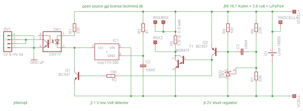
- Detects Vlow (ca. 2,85 volt) and opto coupler patch info to the arduino based BMS controller
- Detects Vhighhigh (4,2 volt) and opto coupler patch info to the arduino BMS controller
- Balancing the cell at Vhigh with a load resistor, switched on with a Darlington transistor
This cell module can be used for electric vehicles with LiFePo4 batteris, just by changing some configuration in the arduino sketch, and a few components on the arduino BMS controller shield.
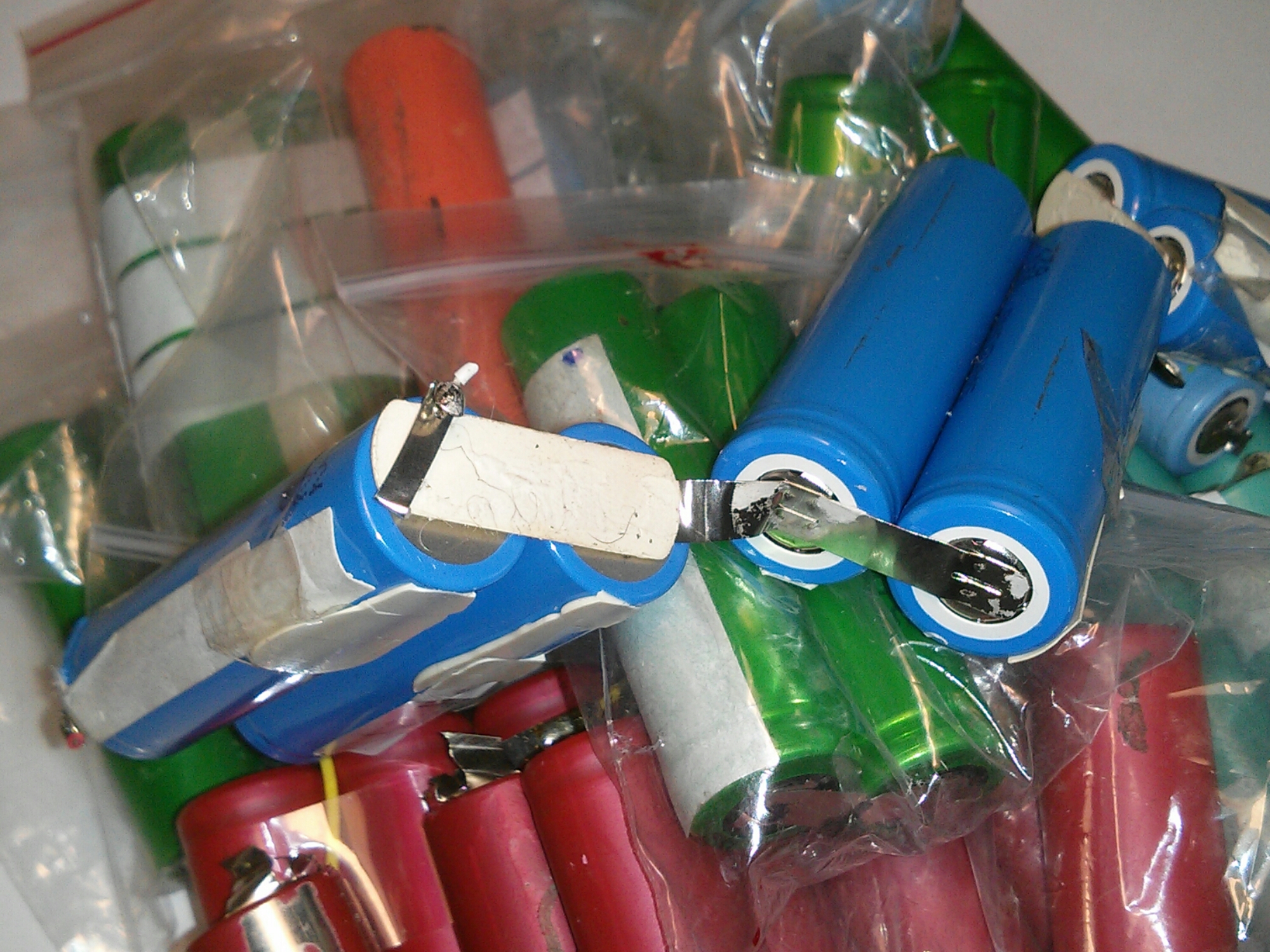
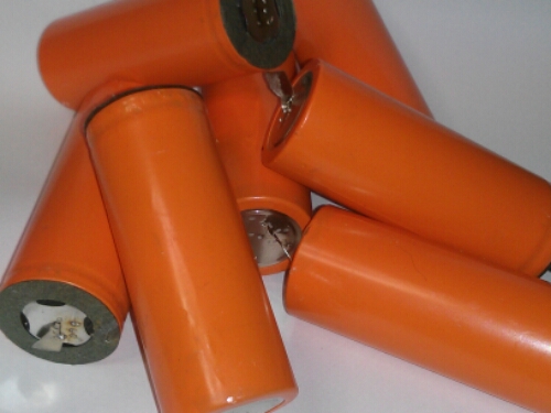
My inspiration for this project came from the raising amount of standard 18650 LiIon cells, i salvage from defect labtop batteries, and other LiIon driven electronic.
I simply hate to trough out things that works. Also i have a electic bicycle, cleaning robots and dream about making a eletric outboud boat motor, using salvaged cells, so i decided to make my own BMS, and use other components i had on the shelf doing nothing.
I had some transistors, power resistors, optocouplers, resistors and more, so thats why this first version is with analog leaded components.
This cell module can be modified to fit the new LTO battetry cell.
the cell module can NOT by it self disable the charger or turn of the load at Vlow. The cell module are not for standalone, they work together with the arduino BMS controller shield.

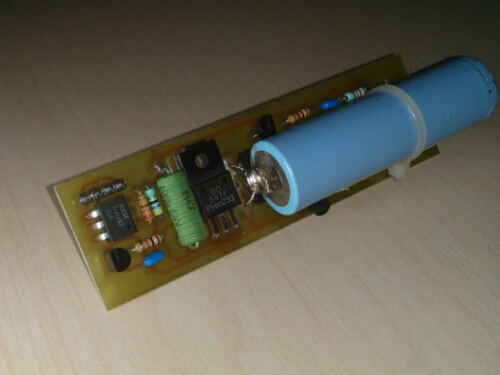
The picture above show the cell module with the 18650 LiIon cell from a dead labtop.
Often more cells in the labtop battery are in fully working condition, or the original cell pcb is defect. It is possible to get hånds of a lot of free LiIon cells for fully working DIY battery packs.


